Mr. Smith Help English version
This is a translation of 'Mr. Smith Help version 2.03 April 30, 1996'. I added some comments and pictures concerning Japanese font issues.
Disclaimer
I assume no liability or responsibility for errors, omissions or ambiguities in this document. Under no circumstances, I am liable for any damages whatever arising out of your use of this document, including direct, indirect, incidental, consequential or punitive damages.
I am glad that you use Mr. Smith.
Mr. Smith is a calculator on the Smith Chart running on PC. I made this software in order to make RF engineers free from a compass and paper-form Smith Chart.
Mr. Smith would let you be familiar with the Smith Chart because it calculates reactance and complex number automatically.
Contents
[The Window]
[Program] Menu
[Marker] Menu
[Rotate] Menu
[Circle] Menu
[Option] Menu
[Print] Menu
[The Window]
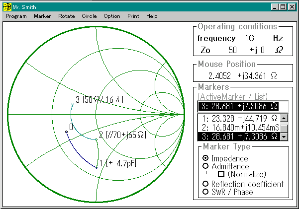
Operating Conditions
You enter an operating condition of calculation here. You click the portion you want to change. Then the cursor appears. You enter a number with a prefix (G,M,k,m,u,n,p) and push the enter-key. You must push the enter-key after changing a parameter here.
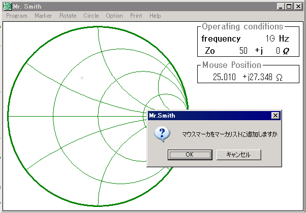
Mouse Position
This number indicates the impedance of the cursor point. If you want to add a cursor point to a marker, click any button of the mouse. Then a confirmation window appears. This asks you whether you add this point to Marker List. The left button is 'OK' and the right button is 'Cancel'.
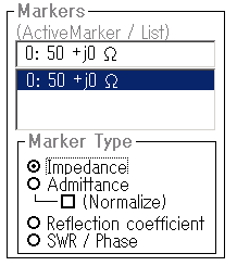
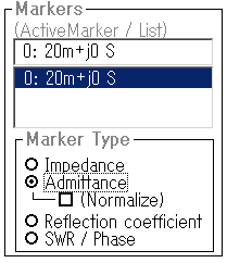
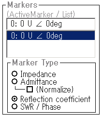
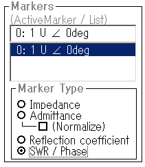
Markers
The list indicates all markers on the chart. The Active Marker is the target to calculate. You can change Active Marker to other markers by clicking a marker entry in the marker list.
You can select a display format of the Active Marker from impedance, admittance, reflection coefficient or SWR/ Phase.
*The angle symbol goes wrong in English language environment. Ohm letter and 'j' may go wrong, too.
[Program] Menu
You can clear the chart. All markers, circles and cursors are cleared.
Mr. Smith closes.
[Marker] Menu
It puts or erases a marker on the chart
You can put a marker with 3 types of format, Impedance (R+jX), admittance (G+jB) and reflection coefficient (mag and angle).
You can enter a marker by clicking cursor point on the chart.
You have to enter the first marker to start calculation.
[Rotate] Menu
It calculates impedance shift from the Active marker by connection of R, C, L or transmission line. The calculation result-impedance destination is added to the marker list and plotted on the chart. The units of value of L and C are Henry and Farad respectively.
You can set the characteristic impedance of a transmission line in spite of Normalized Impedance setting in the Operating Conditions window.
You can set the length of a transmission line with a physical length (electric permittivity=1), electric length or phase angle.
[Circle] Menu
You can put or erase a circle that contacts the Active marker. You can put a constant reactance line, a constant resistance circle, a constant conductance circle, a constant susceptance line or a constant SWR circle.
[Option] Menu
You can choose the chart type from the impedance chart, the admittance chart or the immittance chart. You can set SWR cursor and Q cursor here.
[Print] Menu
Print Menu immediately starts to print the chart and all markers in your default printer.
EOT